Within the ADI chemical thermal storage system, calcium and hydrogen provide a thermally reversible high temperature energy storage solution using
the “heat of formation” of calcium hydride(the heat required to break its chemical bond). Solar generated heat is "used" to separate calcium hydride into its constituent elements, calcium
and hydrogen. This heat energy can be recovered by allowing the hydrogen to recombine with the calcium in an exothermic reaction. In this fashion, the heat is not really used, but stored
for later use. The amount of heat that can be stored using the heat of formation is significantly more than the amount that can be stored using "specific heat" (the heat required to change the
temperature of a substance) or even the "latent heat" (heat required for a phase change of a substance). The heat of formation of calcium hydride is the highest of all the common hydrides.
When calcium hydride is formed, the chemical reaction releases 1.29 kW-hr/kg of heat, which is 20 times the storage capacity (contained in the specific heat) of liquid nitrate salts; the storage medium commonly used in multi-MW solar thermal power-plants today. The calcium hydride (CaH) reaction is sufficiently rapid to allow full charge and discharge within two hours. This is fast when
compared to (for example) potassium nitrate salt systems; which take 6-8 hours for a full charge-discharge cycle (while only storing 3-4 hours of run-time). ADI Solars system enables electrical power
generation at night by using stored thermal energy and it also offers auxiliary power generation capacity in peak usage times, such as in the heat of midday or in the evening. It provides
a cost effective energy storage solution with costs similar to those of pumped hydro. The system is designed to provide economical unsubsidized base-load power from solar. The system has also been designed to integrate directly with the Generation IV nuclear power plants which operate between 900 C and 1100 C. Currently, there is no other product on the market that can utilize the high temperatures of concentrated solar, nuclear or waste gases, and transform it into 24/7 electrical power. The future of renewable energy depends on storage solutions such as this, to enable a
greater reliance on renewable resources and to fully utilize waste materials for broader environmental and economic benefit. The ADI high-temperature chemical thermal storage solution is a
revolutionary invention that will change the renewable energy landscape.
System Description
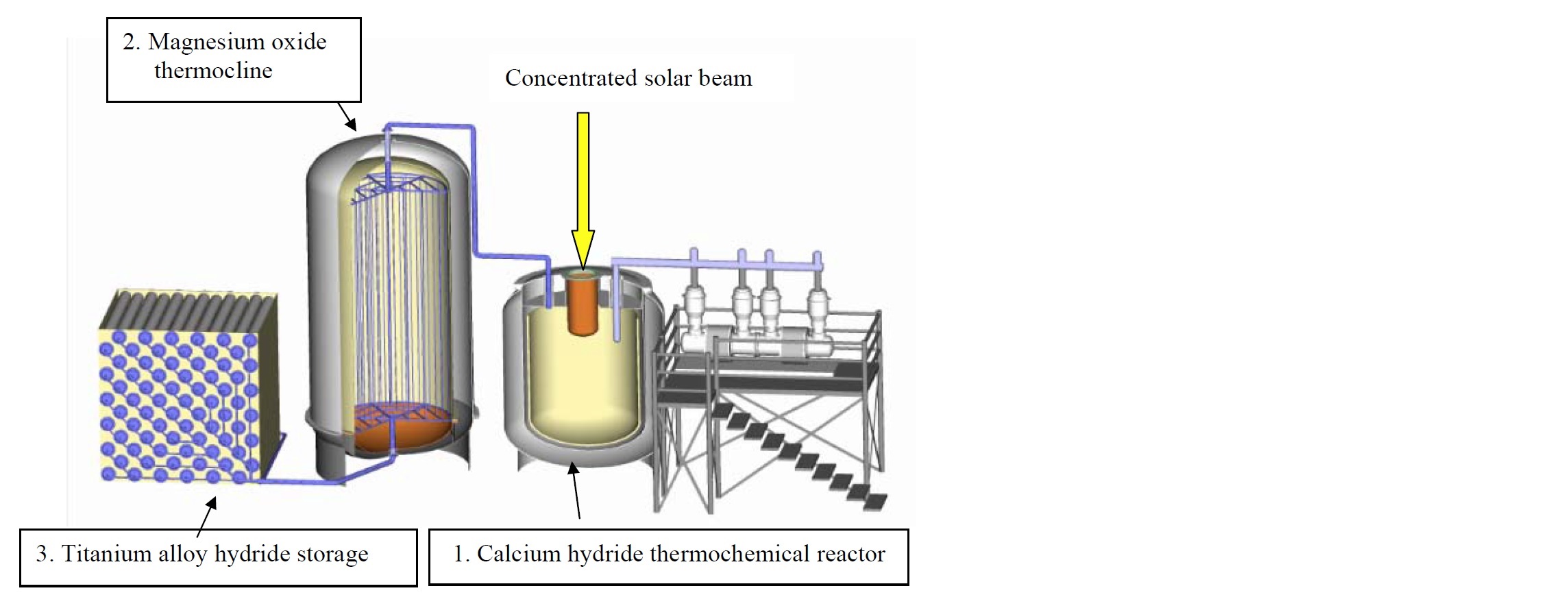
The storage system operates using three components:
1. A (calcium hydride) Reactor, for solar heat absorption and storage via the transformation of calcium hydride into calcium metal and hydrogen gas;
2. a (boron oxide) Thermocline, for storing the excess thermal energy contained in the hydrogen gas before it enters the storage tanks and reheating the hydrogen after it is released
from storage;
3. the (titanium iron hydride) Hydrogen Storage Tanks, for storing the hydrogen and releasing it back into the main reactor tank where it reacts with the calcium metal to release heat energy.
The system operates in 2 modes:
In storage mode, heat liberates hydrogen from calcium hydride. This hydrogen flows from the reactor through the thermocline and into the storage tanks.
In usage mode, hydrogen flows from the storage tanks through the thermocline and into the reactor, where it combines with the calcium and generates heat.
At any given moment, the system will be in one of these two modes - almost never in balance - due to the variable nature of its power inputs and/or output requirements.
Solar Thermal Storage and Heat Engine Generator System.
Reactor
The thermochemical calcium hydride reactor consists of a triple-walled reactor vessel with an inverted molybdenum solar receiver located at the top. It is currently designed for a
down beam solar field configuration (solar reflectors), although the reactor could be used with other solar field configurations. Concentrated solar energy from the solar field is focused into the
receiver through a quartz window built into the top of the receiver. The calcium metal and calcium hydride (CaH2) in the reactor are in direct contact with the receiver, allowing maximum transfer
of the solar energy into the CaH2. The solar energy heats the CaH2 to between 1000 C and 1100 C. At these temperatures the calcium hydride dissociates(splits) into calcium metal (Ca) and
hydrogen gas (H2). In the dissociation reaction, 1.29 kWh of solar energy is absorbed per kg of CaH2 that is split apart. This enables a large amount of solar energy to be absorbed and stored as
potential energy in the separation of hydrogen and calcium metal.
As the hydrogen is liberated, the reactor pressure rises; forcing the hydrogen to exit the reactor towards cooling and storage where the pressure is relieved by the storage process (see below). Not all of the heat is stored. Some heat is siphoned off through a heat pipe heat exchanger(s) to a heat engine for use in generating electricity. When the heat source cools (at night), or when additional
heat is drawn off to meet peak power demands, the pressure in the reactor drops and draws stored hydrogen back into the reactor. There the hydrogen combines with the calcium to form calcium hydride in an exothermic reaction, releasing heat to power the electric generator. In this way, electric power generation continues into the night and also meets peak power demands when required.
As an alternative to solar, the heat source can be thermal output from a nuclear reactor. In this instance, the solar receiver is replaced by a boiler type heat pipe connected to the nuclear
reactor. Heat flowing from the nuclear reactor into ADI Solars thermal storage serves to power ADI Solars generators while simultaneously cooling the nuclear reactor.
Thermocline
In storage mode, hydrogen exiting the CaH reactor is still at high temperature and must be cooled to ambient before it can be stored. The specific heat contained in the hydrogen temperature is small
compared to the heat of formation of calcium hydride. However, this heat it is still significant. Additional efficiency can be achieved by storing this heat and using it to reheat the hydrogen on
its return trip to the reactor (during usage mode). A thermocline system has been included for this purpose, consisting of a network of hydrogen transport tubes within a tank of viscous molten glass.
The hot hydrogen cools as it flows through the network of tubes, transferring its heat to the molten glass. The temperature of the glass stratifies as the hydrogen flow creates high glass temperatures
at the inlet and a steady drop in the glass temperature toward the exit. This effect reverses during usage mode when the cool hydrogen gas from storage flows back through the
thermocline towards the reactor.
ADI Solars thermocline system uses molten boron oxide glass as the primary heat recovery material. Boron oxide is liquid over the temperature range of 450 C to 1860 C, but its melting point can be
lowered to 200 C with an additive. The very low thermal conductivity of boron oxide, allows the glass to maintain a 1000 C vertical temperature gradient with minimal thermal losses. Horizontal graphite disks are held in suspension within the glass to facilitate high heat transfer to and from the hydrogen transport tubes. The high viscosity of the boron oxide glass and the obstruction of the graphite disks prevent convective heat transfer within the tank. The thermocline is contained in a dual shell, with insulation between shells, to minimize radiant heat loss. The thermocline system provides an extremely simple solution for the hydrogen gas thermal energy recovery. Only the hydrogen gas moves within the tank.
Hydrogen Storage Tanks
In storage mode, hydrogen exits the thermocline at ambient temperature and enters the storage tanks. The storage tanks are cylinders filled with a titanium iron powder and immersed in a water
bath for precise temperature control. The pressure produced in the reactor (at the temperature of the bath) tips the storage system past the equilibrium point at which a hydride (TiFeH) forms.
Now solid, the hydrogen captured in the hydride occupies far less volume than hydrogen gas. Consequently, hydrogen continues to flow into the tanks and form titanium iron hydride until storage capacity is reached. At capacity, no further hydrogen can flow, because the hydrogen storage capacity in the tanks is matched to the hydrogen storage capacity in the reactor. When one is depleted, the other is full. Titanium iron hydride provides an economical safe storage for the hydrogen gas until it is drawn back into the reactor
for grid peak load demands.
At night or at peak load, the process is reversed. The reactor pressures drop until the hydride (TiFeH) equilibrium point is reached, at which point the hydride in the storage tank dissociates, releasing hydrogen gas. The inherent pressures cause the hydrogen to flow towards the reactor and the system is in usage mode.
Elegance in Simplicity; Self Regulating
The (reformation) reaction of calcium hydride releases a large amount of thermal energy. This heat allows the reactor temperature to be maintained while heat is drawn off to operate the electric generator. The direction and the rate of the dissociation and reformation reactions are controlled by the hydrogen gas pressure relative to the reactions equilibrium pressure. At pressures below the calcium hydride equilibrium pressure, the calcium hydride splits into calcium and hydrogen and energy is absorbed. At pressures above equilibrium pressure, the
calcium and hydrogen recombine to reform calcium hydride, and energy is released.
One of the elegant features of the system is that it is always stable and self-regulating. For a given pressure, the temperature of the (calcium and calcium hydride solids) in the reactor
controls the reaction direction and the flow of the hydrogen. During the day solar energy is beamed into the reactor through the quartz window and heats the calcium hydride. As the temperature of the
calcium hydride rises, its equilibrium pressure rises above the internal hydrogen pressure; and causes the calcium hydride to split, releasing hydrogen. The system pressure rises in response,
forcing hydrogen gas through the thermocline heat storage and into titanium iron hydride powder at the storage end of the system. When heat flows out of the reactor (at night or under peak demand),
the system pressure drops in response, and draws hydrogen gas out of hydride storage, through thermocline heat recovery, and into the reactor where it reacts with the calcium to produce the requireed heat. In this fashion, the energy storage system is driven by the mismatch in supply (sun) and demand (electric power consumer), the very problem it solves.
The two hydride reactions are well matched in that the same pressure and temperature conditions caused by excess heat input promote both hydrogen production in the reactor and hydrogen
storage in the storage tanks. And the same conditions that are caused by insufficient heat input promote hydrogen release from storage and hydride formation in the reactor. The reaction rates
are sufficiently rapid to meet storage demands without overheat as well as to meet heat demands for the given generator system. These reactions serve to balance demand and supply as long as
maximum storage capacity has not been reached or the system is not "running on empty". When maximum storage capacity is reached, the suns rays must be shuttered from the reactor. When the system is
on empty, then its maximum power output will match the suns input. (Every system has its limits.)
There are no moving parts on the thermal storage system. No pumps are needed for the hydrogen movement. The significant savings in not having to pump the hydrogen makes the complete system more energy efficient and reliable. ADI Solar is currently planning two storage system sizes: a 100 kW unit which stores 3,600 kW-hrs of thermal energy and a 10 MW unit, which stores a total of 360 MW-hrs of thermal energy.
ADI Solar Corp. has developed a patented chemical thermal storage system that:
is 100% self-regulating
provides on-demand delivery of electricity
has 20 times the energy density of other salt nitride systems
is environmentally friendly, releasing no greenhouse gases
can operate at extremely high temperatures to enable the highest levels of efficiency
Side Focusing Heliostat.
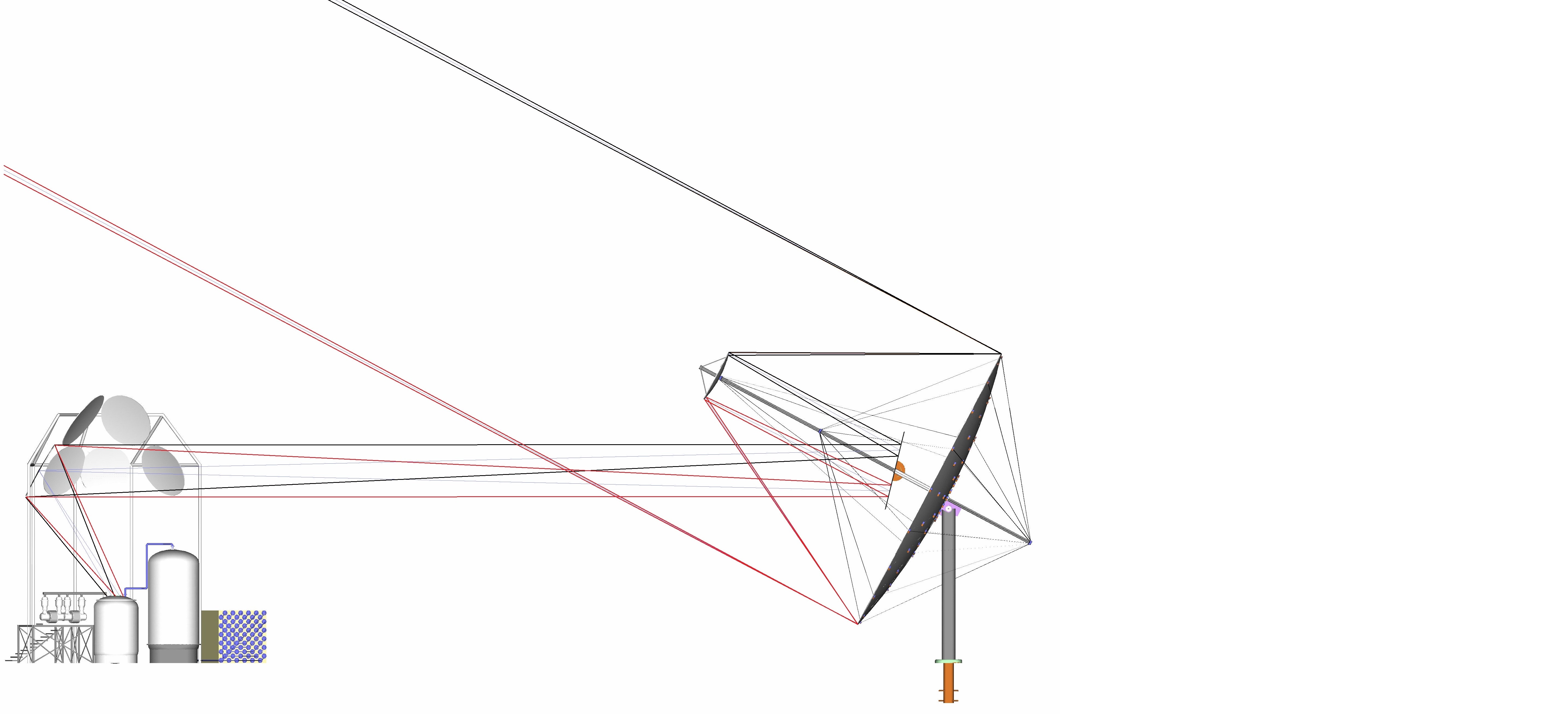
The side focusing helio-stat, developed and patented at ADI Solar, provides a unique solution to the complete CSP system integration. The design uses a parabolic mirror to focus sunlight by a factor of 60:1 onto a hyperbolic mirror which beams the light back along the parabolic mirror axis. This creates a constant diameter light beam that can be transmitted several hundred feet to any CSP system. A flat tilt mirror redirects the focused light beam to an off-axis parabolic down mirror located above the reactor. The down mirror provides the final focusing stage to bring the concentration to 1200:1. Off-axis solar ray tracing programs are used to optimize the beam diameters based on the distance between the heliostat dish and the storage system. Adjustments are made to compensate for the convergent/divergent reflective behavior of the suns rays. ADI Solars (side-focusing heliostat to down beam) configuration has an advantage over typical power tower systems in that it always tracks the sun; eliminating the cosine effect. Power tower systems use large flat heliostats to redirect the suns rays towards a high tower. Their larger mirrors must be over-sized by a factor of 1/cos of the angle of reflection to capture the same amount of sunlight as a parabolic mirror. This is called the cosine effect. The cosine effect averages to a 25% loss, or in ADI Solars case, a 25% advantage over the current market technology. Reflection losses from the additional three small mirrors required for ADI Solars system reduces its cosine advantage only by half. Because they are small and utilize anti-reflection coatings and self-cleaning surfaces to maintain a 96% (per mirror) reflective efficiency, the system's mirrors provide a net 10% efficiency advantage over other heliostat and solar collectors available on the market.
Whether a heliostat is flat or parabolic, it must maintain its shape under load in order to accurately focus the suns rays. Currently marketed designs use truss structures or ribbed surfaces to maintain the mirror shape. While these structural configurations are typically used to add rigidity for minimum weight cost, they still wind up with a significant weight penalty. ADI Solar has taken advantage of the lessons learned in early flight structures by choosing a cable and strut design. The cable and strut construction provide a sufficiently rigid lightweight structure, that reduces both materials cost and actuator power requirements. Strategically located slots in the mirror surface serve to reduce the wind loads, improving stability and also reducing actuator power requirements.
Engine for Converting Heat to Electricity
The discussion so far has been about the core technology behind ADI Solar, solar thermal energy storage. The near term target use of that technology is to supply continuous (uninterrupted) electrical power from solar energy. ADI Solars system captures the sun's energy in the form of heat and discharges it in kind. So to reach our goal, a heat engine is required to
transform heat into electrical power. There are a few engines that might be suitable for this purpose, but only one that we would endorse whole heartedly: the ultra high efficiency Dual
Shell Stirling engine, currently in the final stages of development at ADI Thermal Power Corp. While some inventions happen by accident, others evolve around preceding technologies. Such is the case with ADI Solars calcium hydride reactor, which was developed to integrate with ADI Thermal Powers engine/genset. The reactor operates at extreme temperatures relative to most engines, yet this
temperature is ideally suited to drive ADI Thermals Dual Shell Stirling Engine. (For more information, follow the link.)
Dual Shell Stirling Engine - 100KW Quad.
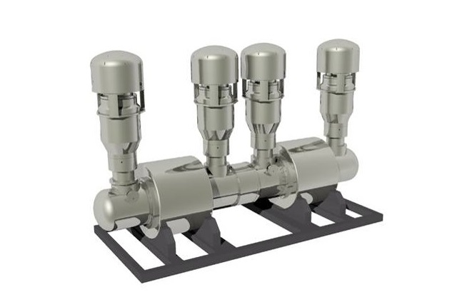
It has long been known that engine efficiency (for all engines) increases with increased operating temperature. High temperature is basically a large amount of heat in a small amount of material. The temperature be can reduced by dilution (adding material) or by use of heat exchangers to accommodate low temperature engines, but only at the cost of efficiency. Using a lower temperature engine would sacrifice efficiency for convenience. And that convenience has another drawback; it would require additional equipment to reduce supply temperature.
The ADI Solar reactor is connected to the ADI Thermal heat engine by means of a heat pipe. A heat pipe is a device designed to transfer large amounts of heat very rapidly in a compact package. It consists of a sealed pipe (the interior of which is lined with a mesh type wicking material) and filled with a quantity of liquid/vapor heat transport material existing at its triple point. In this environment, the heat transport material will change phase from liquid to vapor over a very small temperature range. A few degrees change in temperature from one end to the other creates a pipe where evaporation occurs at the hot end and condensation occurs at the cold end. The vapor travels from the hot to the cold end (transporting heat in the process) and the wicking material returns the liquid condensation to the evaporation end. The process is very rapid and efficient. When connected by heat pipe, the heat engine "siphons" heat from the reactor and uses it to drive an electric generator. Siphon is and apt term, because only the temperature difference between the reactor and engine drives the heat transfer, much as a difference in fluid levels drive a siphoning operation. By using a heat pipe to perform the transfer, it is equivalent to using a very large "heat siphon".
In the simplest terms, a heat engine uses a temperature difference to create motive force (which in turn can be used to drive a generator). The temperature difference is created by a heat source and a cold sink. Left alone, the heat engine will run until the hot side gets cold or the cold side gets hot (i.e.; no temperature difference). Maintaining the temperature difference keeps the heat engine running, and the power output capacity is proportional to the temperature difference. The connection of a heat pipe between solar reactor and heat engine creates a situation where they will equalize in temperature very quickly. When the heat engine is under load (producing electricity), it essentially siphons heat out of the reactor until its hot temperature equalizes to the reactor temperature. If the sun is not supplying enough heat to maintain the reactor temperature, then the reactor pressure drops in response to the heat loss, and more hydrogen is drawn from storage into the reactor. The resulting calcium hydride reaction produces the heat required to maintain the reactor temperature and thus the heat engines electrical output. If the heat of the sun is more than sufficient to maintain the reactor temperature, then hydrogen will be liberated from the CaH and propelled into storage, thereby storing the excess heat.